Story

Perfecting Structure: From X-Braced Steel to Concrete and Back

More than 50 years after inventing an efficient structural system that revolutionized skyscraper design, SOM engineers are improving and adapting it for a changed construction industry.

by Aaron Mazeika

In 1968, as workers hoisted steel beams more than 1,100 feet above Chicago’s lakeshore, the John Hancock Center (now 875 N Michigan Avenue) reached its full height. The achievement would forever change not only Chicago’s skyline, but the entire field of tall building design and engineering. Hancock’s “braced tube” structural system—devised by SOM engineer Fazlur Khan and architect Bruce Graham—introduced a new era of efficient skyscraper design, and now, more than 50 years later, SOM designers continue to improve the concept. 

The origin of Hancock’s iconic structural system can be traced to an earlier Chicago project led by the same design and engineering team: the Dewitt-Chestnut apartment building. For this 42-story tower, Khan devised a structural perimeter of closely spaced concrete columns, which together perform like a thin-walled tube cantilevering from the ground. Dubbed the “framed tube,” this system of perimeter columns was strong enough to absorb strong wind forces, allowing for fewer interior columns spaced further apart. The result: an efficient structure with highly flexible interior spaces. 

Dewitt-Chestnut apartment building, circa 1966. © Hedrich Blessing Photographers
John Hancock Center. Jon Miller © Hedrich Blessing Photographers

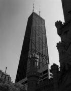
For John Hancock Center, Khan envisioned an even more efficient structural system by replacing the framed tube, as used at Dewitt-Chestnut, with a diagonal steel braced truss on the building’s perimeter, reducing the structural material needed for a tower of this height. The Hancock marked a breakthrough in tall building efficiency—with more improvements to come.

SOM’s research team: In pursuit of efficiency

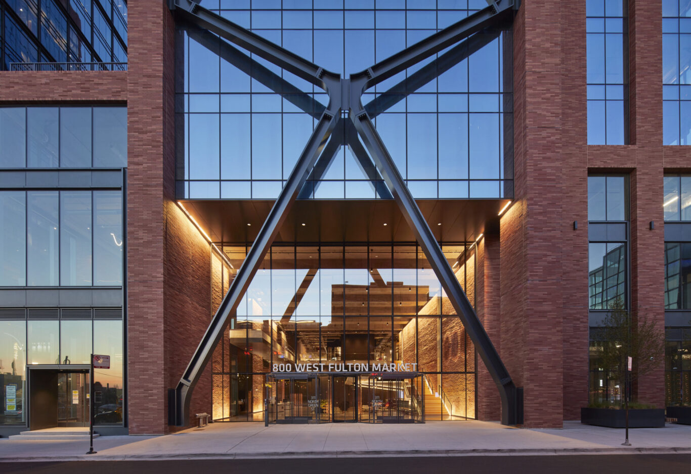
Starting around 2008—approximately 40 years after the construction of the John Hancock Center—SOM partner and structural engineer William F. Baker led a research team to explore optimal truss geometries. One finding was that the Hancock’s X-brace configuration could be improved by moving the central intersection node upwards at the three-quarters height of the braced bay, increasing material efficiency by about 10 percent. (It is interesting to consider that the iconic X-brace geometry of the John Hancock Center would likely have a different design, if the team had had this knowledge at the time.)

Engineers in our Chicago studio test structural performance in our wind tunnel facility. Dave Burk © SOM

A hybrid solution, merging steel and concrete

Our team quickly found opportunities to implement this new knowledge about optimal truss geometries in current projects. The first built example was 100 Mount Street, a 35-story office tower in North Sydney, Australia. Completed in 2019, this reinforced concrete building is designed to maximize daylight and open space, with a high-performance facade and the core offset to one end of the floorplate. To protect the building against wind and seismic forces, a stiff, lateral structural element was required at the opposite end of the building. Applying the new truss geometries developed in SOM’s research, the design team devised a more efficient solution: a cross-braced exoskeleton that strengthens the tower while preserving views.

100 Mount Street
100 Mount Street. © Brett Boardman Photography

While our knowledge of optimal truss geometries has advanced, changes in the construction industry have presented new barriers to the implementation of trussed-tube buildings. Most significant is the transition from steel to reinforced concrete as the preferred construction material for tall buildings. When the John Hancock Center was built, all-steel construction was the method of choice for tall structures, but in the 1980s, as high-strength concrete technology improved, the economics of tall building construction shifted to favor reinforced concrete. The shift from all-steel is significant, because even though steel is ideal for bracing (because steel can be subjected to both tension and compression forces in equal magnitude), it’s difficult to incorporate into a reinforced concrete building due to an incompatibility between the long-term behavior of these two materials. Concrete columns tend to shorten over time when subjected to sustained gravity load—a phenomenon called creep—whereas the creep in the steel braces is insignificant in comparison. Typically, the configuration of the braces allows them to act as an alternate gravity load path to the columns. As the concrete columns creep, this results in a gradual transfer of gravity loads from the columns to the braces, increasing the forces in the braces over time and requiring larger braces and thus, more material.

For 100 Mount Street, our team solved this problem by incorporating a special sliding detail at the central node of the brace. The goal was to isolate the lateral and gravity load paths. If all the gravity load could be kept within the reinforced concrete columns, then the braces would experience only equal and opposite forces due to lateral wind and seismic loads. It would then be a symmetrical geometry system, resisting purely antisymmetric loads. This condition simplifies the load transfer at the central node such that only vertical loads need to be transferred from one side of the central node to the other. A sliding detail consisting of a series of interlocking horizontal plates enables this load transfer but also allows a “release” that isolates the bracing system from gravity loads. When the columns shorten due to creep, the two halves of the central node simply slide slightly toward each other, allowing the columns to shorten without load being transferred to the braces. In a similar way, thermal strains in the braces can be released without inducing axial loads in the bracing.

The central node of the brace at 100 Mount Street, with a sliding detail designed to isolate lateral and gravity load paths.

Simplifying the system: a flexible brace

While the sliding detail at 100 Mount Street was successful and continues to perform as designed, it was complex to fabricate and labor-intensive to install. The design team had an opportunity to improve upon this concept in the design of 800 Fulton Market, completed in Chicago in 2021. Due to the low scale of historic buildings in the surrounding Fulton Market Historic District, the project has protected views to the south and southwest. With a large scale office building immediately to the north, the preferred architectural massing was a rectangular, long-span bar building with a narrow offset core. Early contractor price feedback favored post-tensioned concrete beams over a steel gravity frame, and preliminary analysis suggested supplemental lateral stiffness was required over that provided by the slender core. This led to a design solution similar to 100 Mount Street, with a reinforced concrete gravity frame and a steel braced lateral force resisting system—and therefore an opportunity to improve on the brace node design.

800 Fulton Market. Dave Burk © SOM

At 800 Fulton Market, the team discovered that central node performance objectives could be achieved by replacing the complex sliding mechanism with a simpler geometric mechanism: displacing the central node of the braced bay 24 inches out of plane. The four diagonal brace members in each bay form the edges of a shallow, horizontal pyramid. When the reinforced concrete columns eventually shorten due to creep, the central node simply moves further out of plane, forming a slightly “taller” pyramid. Similarly, when subjected to temperature variations, the braces lengthen and shorten, and the central node automatically moves to reconfigure the geometry without inducing any forces in the bracing. In this way, the forces acting on the braces are limited to wind, which are equal and opposite axial forces, thereby stabilizing the geometry of the central node. When one diagonal is in compression and tends to buckle outwards, the other diagonal is automatically in tension, holding the central node in position.

The brace at 800 Fulton Street accommodates a range of movement due to concrete creep and temperature variations.

To accommodate the brace’s movement, the team developed a flexible steel hinging plate to connect the components, designed to withstand the deformations elastically. To alleviate concerns about fatigue in the welds connecting the hinging plate to the remaining parts of the steel node, the plates are machined down to a dog-bone profile from a thicker plate, significantly reducing the stress levels at the welding points. Beyond the hinging plate, the geometry of the nodes is determined by analytical optimization. Material in areas of low stress is removed, until only the useful material remains. The sculptural form of the nodes is an expression of the forces that flow through them.

Detail of the central node of the brace at 800 Fulton, with its flexible hinging plate.

SOM has a long history of designing buildings through an integrated approach, producing engineering solutions that become the architecture. These buildings tend to be particularly well received by the public—in part, we believe, because the designs enable an inherent understanding of how these buildings work. 800 Fulton Market is a prime example of this integrated design, with research-driven structural systems carefully detailed to optimize performance—artfully expressed to boot.